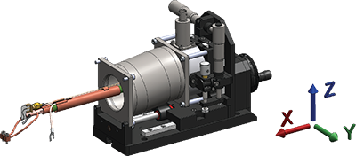
Probing Configurations

Flexible, expandable probing
This comprehensive line of standard micro-manipulated probe arms and accessories to meet a variety of scientific needs. Specific needs of DC, RF, microwave, and optical probing can be accommodated.
- All probes capable of operation over the full sample stage temperature, vacuum and magnetic field range of each probe station model
- For magnetic field probe stations, configurations will be non-magnetic
- One sensor is installed wired to a 6-pin feedthrough in arm location #1 standard for all probe station models. Optional sensors can be ordered (PA-SEN) with the purchase of additional probe arms (PS-PAB-XX).
Probing configurations and their uses
| General purpose DC | Small signal/low noise DC measurements |
| High impedance DC | High impedance/low current leakage measurements |
| RF up to 1 GHz | Typical kHz and MHz RF measurements with banded operation up to 1 can be upgraded to RF/microwave 40 GHz with purchase of a GSG probe |
| RF/microwave up to 40 GHz | Measurements with up to 40 GHz compatible measurement equipment; compatible with DC/RF probes if voltage biasing or lower frequency measurements are needed that do not dictate GSG probing |
| RF/microwave up to 67 GHz | Measurements with 50 and 67 GHz compatible measurement equipment |
| WR-10 THz 75 to 110 GHz | Measurements with 75 to 110 GHz compatible measurement equipment |
| WR-5.1 THz 140 to 220 GHz | Measurements with 140 to 220 GHz compatible measurement equipment |
| Fiber optic probe | Interrogation of samples with optical stimulus, light collection from device |
Probing configurations hardware
| Feedthrough | Probe | Internal cable | Planarization | Customer specifies when ordering | |
| General purpose DC ZN50C-G | 2-lug BNC | ZN50R or ZN50R-CVT | Miniature cryogenic coaxial with grounded shield | no | Probe tip material and radius, variable or fixed temperature |
| High impedance DC ZN50C-T | 3-lug triaxial | ZN50R or ZN50R-CVT | Miniature cryogenic coaxial with shield to triaxial inner guard | no | Probe tip material and radius, variable or fixed temperature |
| RF up to 1 GHz HMWC-XX-00K(-NM) | 2.92 mm (K-connector) | ZN50R or ZN50R-CVT | Semi-rigid coaxial, 2.92 mm with grounded shield | no | Probe tip material and radius, variable or fixed temperature |
| RF/microwave up to 40 GHz HMWC-XX-00K(-NM) | 2.92 mm (K-connector) | 40 GHz ground-signal-ground (GSG) | Semi-rigid coaxial, 2.92 mm with grounded shield | ±5° | GSG pitch spacing |
| RF/microwave up to 67 GHz HMWC-XX-185(-NM) | 1.85 mm (Z-connector) | 67 GHz ground-signal-ground (GSG) | Semi-rigid coaxial, 1.85 mm with grounded shield | ±5° | GSG pitch spacing |
| WR-10 (75 to 110 GHz) MMS-09-THZ-MVNAX-WR10 | WR-10 wavguide flange | Micro-machined ground-signal-ground (GSG) | Internal waveguide | ±3° | Compatible probe (FormFactor) |
| WR-5.1 (140 to 220 GHz) MMS-09-THZ-MVNAX-WR51 | WR-5.1 waveguide flange | Micro-machined ground-signal-ground (GSG) | Internal waveguide | ±3° | Compatible probe (FormFactor) |
| Fiber optic PS-FOA-XXX | See fiber optics section | Non-contact optical probe | Fiber optic | ±3° | Fiber type, operating wavelength and incident angle |
Probing configuration specifications
| Operation frequency | Electrical isolation* | Capacitance | Impedance | S11/S22** (reflection) | S12/S21** (transmission) | |
| General purpose DC | DC to 50 MHz | >100 MΩ | <100 pF | 50 Ω | NA | NA |
| High impedance DC | DC to 50 MHz | >100 GΩ*** | <100 pF | NA | NA | NA |
| RF up to 1 GHz | Up to 1 GHz | >10 MΩ | Not specified | 50 Ω | <-20 dB | <±1 dB |
| RF/microwave up to 40 GHz | Up to 40 GHz | >1 MΩ | Not specified | 50 Ω | <-20 dB | <±1 dB |
| RF/microwave up to 67 GHz | Up to 67 GHz | >1 MΩ | Not specified | 50 Ω | <-20 dB | <±1 dB |
| RF/microwave up to 67 GHz | 75 to 110 GHz | Not specified | Not specified | 50 Ω | <-20 dB | <±1 dB |
| RF/microwave up to 67 GHz | 140 to 220 GHz | Not specified | Not specified | 50 Ω | <-20 dB | <±1 dB |
| Fiber optic | See fiber optics section | NA | NA | NA | NA | NA |
*Isolation measured at 100 V potential between conductive surfaces
**S21 > -10 dB up to 1 GHz, except for a (-40 dB) spike between 400 MHz depending on probe model and placement; S11 < -3 dB up to 1 GHz
***Specified isolation will result in typical leakage currents of <100 fA in a well-designed guarded measurement system
Probe positioning
| X axis | Y axis | Z axis | |
| Travel | 51 mm (2 in) | 25 mm (1 in) | 18 mm (0.7 in) |
| Translation scale | 20 µm | 10 µm | 10 µm |


