More about the Model 625
Current change using internal programming

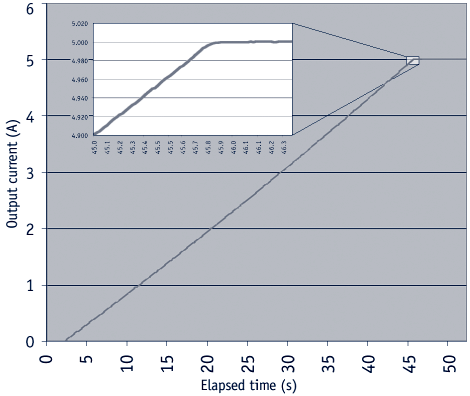
This plot illustrates an actual 5 A current change into an 8.6 H superconducting magnet. A smooth, 95 mA/s ramp is shown with minimal overshoot highlighted in the detail area. (Output current monitor measured at 58.88 Hz rate with a HP 34401 — data multiplied by 10× to obtain output current results.)
Output architecture
True 4-quadrant output capability of the Model 625 is ideal for the charge and discharge cycling of superconducting magnets for both positive and negative fields. Tightly integrated analog control of the 4-quadrant output provides smooth current change with very low overshoot on output change. The Model 625 has the ability to charge and discharge magnets up to a 5 V rate.
True 4-quadrant operation eliminates the need for external switching or operator intervention to reverse the current polarity, significantly simplifying system design. The transition through zero current is smooth and continuous, allowing the user to readily control the magnetic field as polarity changes.
At static fields, output current drift is also kept low by careful attention in the analog control circuits and layout. The high stability and low noise of the Model 625 make it possible in many situations to run experiments without going into persistent mode. This can help to reduce the time necessary to gather data.
The Model 625 output architecture relies on low noise, linear input and output stages. The linear circuitry of the Model 625 permits operation with less electrical noise than switch-mode superconducting magnet power supplies. One key benefit of this architecture is CE compliance to the electromagnetic compatibility (EMC) directive, including the radiated emissions requirement.

Output programming
The Model 625 output current is programmed internally via the keypad or the computer interface, externally by the analog programming input, or by the sum of the external and internal settings. For the more popular internal programming, the Model 625 incorporates a proprietary digital-to-analog converter (DAC) that is monotonic over the entire output range and provides a resolution of 0.1 mA.
The Model 625 generates extremely smooth and continuous ramps with virtually no overshoot. The digitally generated constant current ramp rate is variable between 0.1 mA/s and 99.999 A/s. To assure a smooth ramp rate, the power supply updates the high-resolution DAC 27 times per second. A low-pass filter on the output DAC smooths the transitions at step changes during ramping. Ramping can also be initiated by the trigger input.
The output compliance voltage of the Model 625 is settable to a value between 0.1 V and 5 V, with a 100 µV resolution. The voltage setting is an absolute setting, so a 2 V setting will limit the output to greater +2.0 V.
Output readings
The Model 625 provides high-resolution output readings. The output current reading reflects the actual current in the magnet, and has a resolution of 0.1 mA. The output voltage reading reports the voltage at the output terminals with a resolution of 100 µV. A remote voltage reading is also available to more accurately represent the magnet voltage by bypassing voltage drops in the leads connecting the power supply to the magnet. All output readings can be prominently displayed on the front panel and read over the computer interface.
Protection
Managing the stored energy in superconducting magnets necessitates several different types of protection. The Model 625 continuously monitors the load, line voltage, and internal circuits for signs of trouble. Any change outside of the expected operating limits triggers the supply to bring the output to zero in a fail-safe mode. When line power is lost, the output crowbar (SCR) will activate and maintain control of the magnet, discharging at a rate of 1 V until it reaches zero.
Quench detection is necessary to alert the user and to protect the magnet system. The Model 625 uses a basic and reliable method for detecting a quench. If the current changes at a rate greater than the current step limit set by the operator, a quench is detected and the output current is safely set to zero.
The remote inhibit input allows an external device to immediately set the output current to zero in case of a failure. This input is normally tied to an external quench detection circuit, the fault output of a second power supply, or an emergency shutdown button. The fault output is a relay contact that closes when a fault condition occurs. The contact closure alerts other system components of the fault.
Parallel operation
If an application requires more output current than a single Model 625 can provide, two supplies can be connected in parallel for 120 A/5 V operation. Each unit is programmed for half of the total output current, operates independently, and retains 0.1 mA resolution at 60 A operation. When the units are properly configured, either unit can detect a fault, protect itself, and issue a fault output signaling the other unit to automatically enter the proper protection mode.
Persistent switch heater output
The integrated persistent switch heater output is a controlled DC current source capable of driving most switch heaters. It sources from 10 mA to 125 mA with a setting resolution of 1 mA and selectable compliance voltage of 12 V or 21 V. The minimum load that the persistent switch heater can drive is 10 Ω. Persistent mode operation is integrated into the instrument firmware to prevent mis-operation of the magnet.
Interfaces
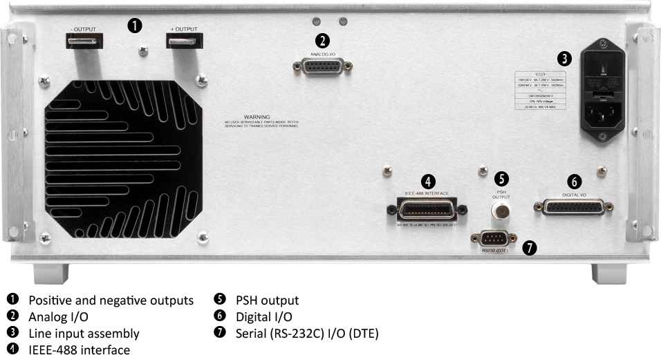
The Model 625 includes IEEE-488 and RS-232C computer interfaces that provide access to operating data, stored parameters, and remote control of all front panel operating functions. In addition, the Model 625 includes a trigger function that is used to start an output current ramp.When the trigger is activated, either by an external trigger or by computer interface command, the power supply will begin ramping to the new setpoint.
The Model 625 provides two analog outputs to monitor the output current and voltage. Each output is a buffered, differential, analog voltage representation of the signal being monitored. The current monitor has a sensitivity of 1 V = 10 A, while the voltage monitor has a sensitivity of 1 V = 1 V.
Display and keypad
The Model 625 incorporates a large 8-line by 40-character vacuum fluorescent display. Output current, calculated field in tesla or gauss, output voltage, and remote voltage sense readings can be displayed simultaneously. Five LEDs on the front panel provide quick verification of instrument status, including ramping, compliance, fault, PSH status, and computer interface mode. Error conditions are indicated on the main display along with an audible beeper. Extended error descriptions are available under the Status key.
The keypad is arranged logically to separate the different functions of the instrument. The most common functions of the power supply are accessed using a single button press. The keypad can be locked to either lock out all changes or to lock out just the instrument setup parameters allowing the output of the power supply to be changed.

Current and voltage settings, current and voltage readings, ramp rate, voltage sense, and persistent switch heater status and instrument status displayed simultaneously

The instrument can be set up to show calculated field along with output field setting, current ramp rate, the output current reading, the output current setting, the output voltage setting, the voltage compliance setting, and the remote voltage sense reading.

